
| Command name: FRAMING_LIST | Space(s): Layouts space, Detail spaces* |
| Purpose: Opens a dialog to view or adjust a selected item’s settings. The dialog’s settings depend on the type of item selected. This is a frequently used command. | |
|
Usage: |
|
| 1. Type LI and press Enter. | |
| 2. Select item(s) and press Enter. A relevant dialog opens (scroll for dialog-specific info). | |
|
3. Make changes and click Amend, Change, or Keep or (for wall panels in the Layouts space) click Re-Code to open the Panel Coding Editor. Or double-click an item to open its dialog and make changes. |
|
|
Additional info:
• NOTE! Text in some dialogs will appear in red if the selected item's Engineering Status is FAILED.
|
|
Bath Editor dialog
Opens when you use the LI command on (or double-click) a bath panel. Allows you to change the rail height of a selected bath panel. Type PBN to add a bath panel and noggin.
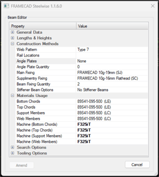
Beam Editor dialog
Opens when you use the LI command on (or double-click) a beam in a wall panel layout.
| General Data | |
| Allows you to change the System Name, Beam Category, Beam Name, Beam Top RL, Beam Base RL, Beam Height, Beam Width, Drafting Colour, Detail This Item for a selected beam (See ADD Beam for more) plus: | |
| Beam Label | Changes the label prefix (as set in PSET) or number for a selected beam. |
| Zone Location | Assigns selected beam(s) to an area. Zone must be three or more characters and not start with x or z. |
| Redline Text |
Sets text that will appear diagonally over any selected beam in its detail sheet. |
| Treats as Non Structural | N/A. Do not use. |
| Show in 3D Model | Renders selected beam(s) in the Model space when you type A3D or P3D. |
| Text Height | Changes the label text height (as set in BSET) for selected beam(s). |
| Convert to panel | Changes a selected beam to a coded wall panel. |
| Go to detailed beam | Navigates to a selected beam’s detail sheet (if one exists). |
| Reset Labels | Removes labels from selected beam(s). |
| Lengths and Height | |||||||
| Raking Angle | Sets the angle the selected beam(s). | ||||||
| Starting End Type |
If Raking Angle has a value:
|
||||||
| Finishing End Type | |||||||
| Drafting Length | Shows a beam’s apparent length. This will equal the Cutting Length value if no lap length and/or clearance is applied. | ||||||
| Cutting Length | Shows a beam’s actual length if a lap length and/or clearance is applied. | ||||||
| Clearance | Enter a positive value to remove a specific length from both ends of a beam. Enter a negative value to move a beam by a specific distance from its starting point. | ||||||
| Left Lap Length | Laps an end of a beam over a wall by a specified length. | ||||||
| Right Lap Length | |||||||
| Beam Weight (kg/lb) | Shows the weight of a beam based on its material, type, and dimensions. |
| Construction Methods | (appears for webbed beams only) |
| Web Pattern |
Sets how web members will be positioned between chords at assembly. |
| Rail Locations | Sets the distance from the bottom plate to add horizontal member(s). |
| Angle Plates | Adds up to two lintels (per chord) with specified thickness/dimensions. |
| Angle Plate Quantity | |
| Main Fixing | Specifies the type of screw to use with dimple holes. |
| Supplementary Fixing | Specifies the type of screw to use if a joint requires additional screws. |
| Beam Fixing Quantity | Sets the number of screws required to fix each side of a beam to a wall. |
| Stiffener Beam Options | Adds a stiffening member over the top chord, under the bottom chord, or both. Steelwise adjusts the beam to maintain its set Beam Height. |
| Materials Usage | (appears for webbed beams only) |
| Allows you to change the material and roll-former type to use for Bottom Chords, Top Chords, Support Members, and Web Members for selected beam(s). | |
Brace Editor dialog
Opens when you use the LI command on (or double-click) a brace in a wall panel layout.
| Brace Information | |
| Displays Brace Type and Brace Length, X and Y Contribution (i.e., resistance per axis), Racking Resistance (i.e., resistance to sideways deformation), Overturning Resistance (i.e., resistance to rotation or tipping over), and Overall Capacity (i.e., overall resistance). | |
| Brace Material | (For strap braces only) Changes the material and switches between single and double strap. |
| Brace Quantity | |
| Reverse Brace | (For k-braces and bridging braces only) Changes the direction of the brace. |
Fixing Details dialog
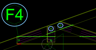
Appears when you use the LI command on (or double-click) a screw or supplementary screw indicator in a detail sheet.
| Product Information | |
| Joint Type | Shows if selected screw(s) are for a Main, Web, Rail or Boxing joint. |
| Main screw type | Shows the screw type to be used when there is a dimple hole. |
| Sub screw type | Shows the type to be used if supplementary screws are indicated. |
| Drafting Colour | Changes the colour used in the detail sheet for selected screw(s). |
| Qty of main fixings | Shows total number of screws to use with dimple holes for joint. |
| Qty of sub fixings | Shows total number of supplementary screws, if indicated, for joint. |
| Total qty of fixings used | Shows total number of screws required for joint. |
| Strengths |
| Shows Total Capacity and Joint Load (when applicable). |
Floor Member Editor dialog
Appears when you use the LI command on (or double click) a joist in a floor layout (or when you type JJD and double-click an item in the left-hand Members list in the Joist Builder dialog).
| General Information | ||||||||
|
Allows you to change the System Name (i.e., data file), Member Name, Category, Member Usage, and Member Type (see Add items command for details). |
||||||||
| Label | Changes the label prefix (as set in JSET) or number of the selected joist | |||||||
| Zone Location | Assigns selected joist(s) to an area. Note: must be three or more characters and not start with x or z. | |||||||
| Member Height | Shows and (webbed joists only) allows you to change the joist height. | |||||||
| Member Width | Allows you to change the width of selected joist(s). | |||||||
| Length Drawn | Shows the joist's length. | |||||||
| Clearance Allowed | Shortens a joist at each end by a specified value. | |||||||
| Nominal Weight | Shows the approximate weight of a joist based on type, material thickness, and dimensions. | |||||||
| Layout Colour | Changes the colour (as set in JSET) used in Layouts space for the selected joist(s). | |||||||
| Reduced Level | Changes the elevation (as set in JSET) measured from the ground level to top of the joist or (for webbed joists) the top of the top chord. | |||||||
| Redline Text | Specifies text to appear diagonally over a joist in its detail sheet. | |||||||
| Engineering Status |
|
|||||||
| Detail this item | Sets Steelwise to create detail sheet(s) for selected joist(s) (when you type JJD) or removes labels from joist(s) and prevents detail sheets from being created. | |||||||
| Show in 3D Model | Renders a selected joist in the Model space when you type A3D or J3D. | |||||||
| Joist Spacing | Changes the distance (as set in JSET) between selected joist(s) and neighboring joists. | |||||||
| Oncoming Web Align | (For webbed beam bearers and joist beams only) Adds a vertical web to provide a fixing location wherever it is intersected by a joist. | |||||||
| Double Webs to Supports | Places two vertical members in a webbed joist at each edge of an underlying support line (as determined by the line’s support width). (See JSET for more info.) | |||||||
| Hide Joist Labels | Hides or shows automatically-generated joist labels and changes the joist label text size. | |||||||
| Text Height | ||||||||
| Material Information |
| Allows you to change the material and roll-former type to use or (for a webbed joist) change the material and roll-former type to use for the Bottom Chord, Top Chord, Vertical Member, and Web Member, change the web pattern, web spacing, and top/bottom chord quantity. |
|
Fixing Information |
| Sets the main Screw Type, the Additional Screws type, and Screw Quantity to use for the selected joist(s) wherever the joists/joist members are fixed together. |
| Loading Information | |
| Shows the applied loads and bending and distribution factors for the selected joist. | |
| Point Load Type | (Webbed joists only) Specifies where on selected joist(s) to apply the Design Point Load (Webbed joists only). |
| Deflection Limits |
| Shows preset engineering values for selected joist(s). |
| Batten Information |
| (For BOM purposes only) Sets material, length, laps, screw types and quantity that will be used with selected joists. |
| Tooling Options |
| See Panel settings command for information. |
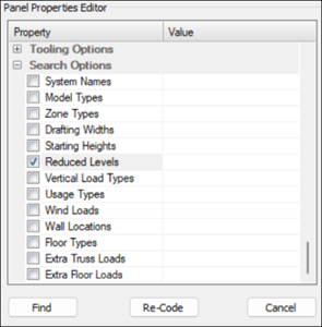
| Search Options |
| Select option(s) and click Find to identify matching joists. |
Gridline Editor
Appears when you use the LI command on (or double click) a gridline created with the GL (GRIDLINE) command.
| Gridline Editor | |
| Allows you to change the Gridline Layer, Gridline Linetype, Gridline Line Colour, Gridline Text Colour, Show Finishing Marker, Show Gridline Line, and Text Height settings for the selected gridline. (See BSET for more info). | |
| Marker Text | Sets the number or letter of a selected gridline. |
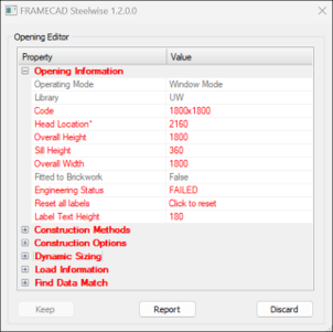
Opening Editor
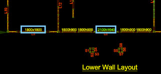
Appears when you use the LI command on (or double-click) the dimensions for an opening in a layout.
| Opening Information | |||||||||
| Operating Mode | Shows the opening's usage. | ||||||||
| Library |
Shows if the opening is a user-defined window or door or (for pre-defined openings using the ADD command) the source of the opening's configuration. |
||||||||
| Head Location | Sets the distance from the bottom of a window’s head member to the bottom of the wall’s top plate. Changing the Head Location will change the Sill Height (if possible) to preserve the Overall Height. | ||||||||
| Overall Height | Sets the distance from the top of the sill to the bottom of the head (for windows) or the bottom of the wall’s bottom plate to the bottom of the head (for doors). Changing this will change the Sill Height for windows. | ||||||||
| Sill Height | Sets the distance from the bottom of the wall’s bottom plate to the top of a window’s sill member. Changing the Sill Height will change the Head Location (if possible) to preserve the Overall Height. | ||||||||
| Overall Width | Sets the distance between the insides of the two studs on either side of the opening. Changing this value will increase or decrease the width equally relative to the opening’s centerline. | ||||||||
| Fitted to Brickwork | Shows if the opening has been fitted to suit brickwork using the PFB command. | ||||||||
| Engineering Status |
To reset an amended opening to its Passed state, select Unknown, click Keep, and (in Detail spaces only) type PUA to update the opening. |
||||||||
| Reset All Labels |
Changes all labels for user-defined openings in the Layouts space from W+H (e.g., 1500w1200) to HxW (e.g., 1200x1500).
|
||||||||
| Label Text Height |
Changes the selected opening’s label text size.
|
| Construction Options | |||||||||
| Top Noggin | Allows you to include or exclude noggins in the opening or to defer to data file for noggin settings. | ||||||||
| Bottom Noggin | |||||||||
| Head Check Calcs |
Sets when Steelwise checks if a head and/or sill has sufficient wind resistance and if a stiffener will be added automatically to compensate.
|
||||||||
| Sill Check Calcs | |||||||||
| Head Stiffener |
Specifies if a stiffener will be required or not. If required (and the related Check Calcs field is set to Always calculate this value) then Steelwise will add one automatically. |
||||||||
| Sill Stiffener | |||||||||
| Extend Head Stiffener |
Determines if an added stiffener will end at or extend over jamb studs. |
||||||||
| Extend Sill Stiffener | |||||||||
| Align Head Studs |
Aligns vertical members with trusses if Webbed Head is selected for Head Type and the selected Web Pattern has vertical members. NOTE: Places studs at point loads only. For other stud placement requirements, type PSA. |
||||||||
| Max Web Spacing |
Sets a maximum space between vertical members if Webbed Head is selected for Head Type and the selected Web Pattern has vertical members. |
||||||||
| Bottom Plate Cutout |
Allows you to include or exclude notches on both ends of the bottom plate of an opening or to defer to the data file for cutout requirements. |
||||||||
| Min Studs Left |
Sets the minimum number of studs the selected opening will have on either side. |
||||||||
| Min Studs Right | |||||||||
| Head and Sill End Jack Studs |
Adds end jacks to the head or to the head and sill. |
| Dynamic Sizing |
|
Shows the opening height and width, and allows you to add clearances to the top, bottom, and/or sides of the opening. |
| Load Information |
|
Shows the dead, live, and wind loads applied to the opening (if related trusses have been built). |
Panel Coding Editor
Appears when you use the LI command on (or double-click) an uncoded wall (i.e., a wall drawn using the PD command but not yet coded.)
See the ADD items command for info.
Panel Properties Editor
Appears when you use LI command on (or double-click) a coded wall (or when you type PPD and double-click an item in the left-hand list in the Panel Builder dialog).
| General Information | |
| System Name | See PSET for info. |
| Model Filter | |
| Model Type | |
| Panel Label | Changes the label prefix (as set in PSET) or number for any selected coded wall. |
| Zone Location | Assigns selected wall(s) to an area. Note: must be three or more characters and not start with x or z. |
| Drafting Width | See PSET for info. |
| Actual Width | |
| Panel End Clearance | Reduces the length (and moves end studs) of the selected wall panel by up to 5mm (3/16”) on both ends, for a total of 10mm (3/8”) max. Openings or pockets within 100mm (≈4”) of either end will move by the set amount. |
| Length Drawn | Shows the length of a selected wall panel. |
|
Maximum Length |
Shows the maximum length for wall panels (as set in PSET). |
| Drafting Colour | Sets the color to use in Layouts for the selected wall(s). |
| Redline Text | Sets text that will appear diagonally over the selected wall in its detail sheet. |
| Detail This Item | Sets Steelwise to create a detail sheet for the wall panel (when you type PPD) instead of excluding it and removing its label (if one exists) from Layouts. |
| Show in 3D Model | Renders the selected wall panel in the Model space when you type A3D or P3D. |
| Convert to Beam | Opens a Panel Coding Editor dialog to change the selected wall to a beam with specified settings. |
| Go to detailed panel | Navigates to a selected wall panel’s detail sheet (if one exists). |
| Reset Labels | Removes labels from selected wall panel(s). |
| Label Text Height | Changes the selected wall panel’s label text size. |
| Notching Information | |
| Starting End Top Height | Sets dimensions and notching method for a notch at either end of the selected wall panel. |
| Starting End Base Height | |
|
Start Length |
|
| Starting End Type | |
| Finishing End Top Height | |
|
Finishing End Base Height |
|
|
Finishing End Type |
| Materials Information |
| Specifies the material and roll-former to be used for plates, heads, sills, noggins, studs, braces, webbing, blocking, and bath rails. |
| Fixings Information |
| Sets what screws will be used for walls, braces, and lintels (at dimple holes) and what screws will be used for supplementary fixings (at hand-drilled holes). |
| Tooling Options |
| See Panel settings command for information. |
Sheet Label Editor
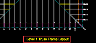
Appears when you use the LI command on (or double click) a layout label (automatically generated when you use the LA command in Layouts).
| Sheet Label Options | |
| Text Prefix | Sets the label prefix (i.e., the level or floor name) if Use Sheet Level ID’s is set to True. |
| Text Suffix | Changes the label suffix (i.e., the name of the layout). |
| Use Sheet ID's | Allows you to show or hide the set Text Prefix (i.e., level or floor name) for the border label. |
| Also allows you to set the label’s Layer Name and change the label’s Text Height and Text Colour. | |
Truss Editor
Appears when you use LI on (or double-click) a truss (or when you type TTD and double-click an item in the left-hand Truss Results list in the Truss Builder dialog).
| General Information | ||||||||
| Allows you to change the System Name or Model Name (as set in TSET) and Truss Type (as set when added) for a selected truss. | ||||||||
| Truss Orientation |
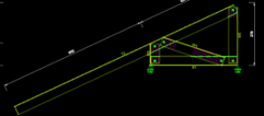
Shows from which side a truss is viewed in its detail sheet (indicated in Layouts by a rectangle). NOTE: All inline-system trusses have Left Handed orientation; back-to-back trusses can have Right Handed orientation, depending on which way the webs facing (as set in TSET). Below shows a truss with Right Handed orientation and how it appears in its detail sheet.
|
|||||||
| Roof Load | Changes the loads and wind speed/category (as set in TSET) for a selected truss. | |||||||
| Wind Speed | ||||||||
| Ground Snow load | ||||||||
| Truss Label | Changes the label prefix (as set in TSET) or number of a selected truss. | |||||||
| Drafting Colour | Sets the color to use in Layouts for a selected truss. | |||||||
| Redline Text | Sets text that will appear diagonally over a selected truss in its detail sheet. | |||||||
| Engineering Status |
|
|||||||
| Go to detailed truss |
Navigates to a selected truss' detail sheet (if one exists).
|
|||||||
| Detail This Item |
Sets Steelwise to create a detail sheet for the truss (when you type TTD) instead of excluding it and removing its label (if one exists) from Layouts.
|
|||||||
| Show in 3D Model |
Renders the selected truss(es) in the Model space when you type A3D or T3D.
|
|||||||
| Detailed Options | |
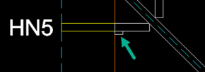
| Shows the Truss Quantity Required, Final Quantity Required, and Support Locations for the selected truss (which will be reflected in its detail sheet). | |
| Extra Quantity Required | Allows you to increase the quantity of the truss to be produced (without changing the truss layout). |
| Construction Information | |
| Truss Spacing |
Allows you to change the actual spacing applied to a selected truss and used for the calculation of applied loads. |
| End Web Setback | Manually sets the location of the end vertical web member of a half truss or of a stop ended truss (i.e., a truss where editing results in an end that is cut off before the normal heel position). |
| Span Information | |
| Nominal Span | Shows the original length of the selected truss and the final length of the truss after a selected truss length was changed (e.g., when typing ML) |
| Final Span | |
| Left Cut Off | Shows how much length was cut off from either end of a selected truss. |
| Right Cut Off | |
| Drafting Width |
Sets how wide the truss appears in a layout (for visual and dimensioning purposes only) |
| Pitch Information | |
| Left Pitch | Allows you to change the angle on the left end or right end of the selected truss. |
| Right Pitch | |
| Ceiling Pitch | Allows you to set an angle for fixing a ceiling to the bottom chord of a selected truss. |
| Materials |
|
Specifies the material and roll-former type to be used to manufacture the bottom chord, top chord, web members and rails for the selected truss, and specifies if the truss requires a single or double top or bottom chord. |
| Tooling Options |
| See Panel settings command for information. |
|
Fixings |
| Sets what screws will be used (at dimple holes) for main, web, and rail joints, and for additional fixings (at hand-drilled holes), and the quantity of screws required for chords and webs. Also sets spacing for screws for boxed members. |
| Editing Tools | |
| Split Height | Changes the maximum height and required gap (as set in TSET) to split a selected truss horizontally. |
| Split Gap | |
| Split Pitch |
Sets a pitch for the top hat truss created when a selected truss is split horizontally. |
| Split in Height | Splits a selected truss horizontally into a truncated truss at bottom and a saddle truss (or top hat) at top (with the specified split gap and split pitch). |
| Effective Length Factors | (changes factors for calculating truss strength) |
| Bottom Chord Restraint | The spacing between restraining battens. |
| Effective Length (Kx) |
The effective length factor for the x-axis and y-axis for the chords in a selected truss. |
| Effective Length (Ky) | |
| Torsional Length (Kt) | The factor used for calculating the effective length of chords in a selected truss for resisting twisting. |