
Copy to Model space (C3D)
| Command name: CopyModel | Space(s): Layouts space |
|
Purpose: Copies selected item(s) from the Layouts space to the same location (relative to a reference point) in the Model space. |
|
|
Usage: |
|
|
1. Type C3D and press Enter. Steelwise switches to the Model space, centered on the copied item(s). |
|
Clear border (CB)
| Command name: ClearBorder | Space(s): Layouts space |
| Purpose: Removes all items from a selected border. | |
| Usage: | |
| 1. Focus on a border. 2. Type CB and press Enter. |
|
Copy posts (CC)
| Command name: COPYPOST | Space(s): Layouts space |
| Purpose: Copies post(s) (i.e., columns) from a border with a wall layout to a selected location in another border. NOTE! Steelwise removes all system-generated data from copied posts. | |
|
Usage: |
|
|
1. Focus on a border with a wall layout containing posts. |
|
Create support line (CSL)
| Command name: CREATE_SUPPORT | Space(s): Layouts space |
| Purpose: Copies walls or beams from a border with a wall layout and pastes them as support lines in another border. Used to create joist layouts and to ensure loads transfer to underlying load-bearing walls. | |
| Usage: | |
|
1. Focus on a border with a wall layout. |
|
Center items (CTR)
| Command name: CENTERED | Space(s): Layouts space; Detail spaces |
| Purpose: Centers selected items in a border or detail sheet. | |
|
Usage: |
|
|
1. Focus on a border or detail sheet. |
|
Copy view (CV)
| Command name: COPYVIEW | Space(s): Layouts space |
| Purpose: Copies selected items from one border to the same location in another border. | |
| Usage: | |
| 1. Focus on a border with items to copy. 2. Type CV and press Enter. 3. Select item(s) and press Enter. 4. Select a border to copy to. |
|
|
Additional info: • NOTE! The COPYVIEW command does not copy labels. |
|
Restore Steelwise functionality (DO_ONCE)
| Command name: DO_ONCE | Space(s): Layouts space; Detail space(s) |
| Purpose: Restores Steelwise to its default CAD, menus, and command functionality | |
| Usage: • Type DO_ONCE and press Enter. |
|
|
Additional Info: • Read more on restoring defaults and missing functionality. |
|
Explicit tool input (ET)
| Command name: TOOL_ACTION | Space(s): Detail spaces |
|
Purpose: |
|
|
Usage: Adding tooling to a member: |
|
| 1. Type ET and press Enter. A dialog appears.
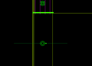
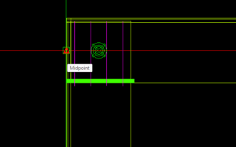
Extending a member with added tooling: 1. Type ET and press Enter. A dialog appears.
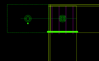
The member end is extended by the value set for Material Increase, with tooling placed at the distance specified for Tool Location.
|
|
|
Additional info: • * NOTE! The System Name (i.e., data file) determines your available actions, |
|
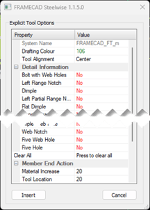 2. Select tooling action(s)* and click Insert.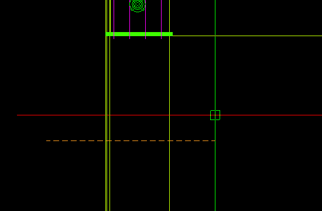
| Explicit Tools Options | |
| System Name | Shows the data file in use. Cannot be changed via this dialog. |
| Drafting Color | Sets what color to use for the tooling indicator line. Click the ellipsis (...) to change colors. |
| Tool Alignment | (For notches and service holes only) Sets where to place a tooling action relative to the line you draw through member(s). |
| Detail Information | (Shows available tooling actions, as determined by the data file in use.) | |||||||||||||||||||||
| Possible tooling actions: |
|
| Member End Action | (Sets what happens when you hold Alt |
| Material Increase | Sets the length by which to extend the selected end of a member. |
| Tool Location | Sets the distance from the end of an extended member to add tooling action. |
Find a panel or frame (FFIND)
| Command name: FIND_ITEM | Space(s): Layouts space; Detail spaces |
|
Purpose: Locates a specified, labeled wall panel, joist, or truss in its layout or identifies its detail sheet. |
|
|
Usage: To locate an item in its layout (in Layouts space) or to identify its detail sheet (in Detail spaces): |
|
|
1. Type FFIND and press Enter. A marker appears in |
|
|
Additional info: |
|
Add gridlines (GL)
| Command name: GRIDLINE | Space(s): Layouts space; Detail spaces |
| Purpose: Allows you to create a grid by drawing a series of alphanumerically identified horizontal and/or vertical lines (as set in BSET). | |
| Usage: | |
| 1. Type GL and press Enter. 2. Select a start and end point for the first line and press Enter. This sets the length of each subsequent line.* 3. For each subsequent line, select a location and press Enter. 4. Press Enter again to end the command. |
|
|
Additional info: • *NOTE! Steelwise prompts you to enter a letter/number if Prompt for Marker text is set to Yes in BSET. |
|
Integrity checks (IC)
| Command name: MEMBER_CHECK | Space(s): Layouts space |
|
Purpose: Use this command to identify drafting and layout errors when creating wall layouts. |
|
| Usage: | |
|
With wall layout border in focus: |
|
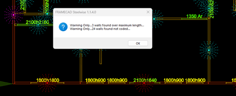
| Possible results of an integrity check | ||
| Issue message | Severity | Marker color |
| No reference points/x reference points within view | Critical Error | N/A |
| wall(s) not coded | Warning only | Cyan |
| wall(s) not labelled | Yellow | |
| wall(s) found not touching others | Blue | |
| walls found overlapping others | Yellow | |
| wall(s) over maximum length | Magenta | |
| wall(s) over trucking limits | Magenta | |
| opening(s) across two panels | Yellow | |
| brace(s) across openings | Yellow | |
| wall(s) with no dead loads | Blue | |
| wall(s) found with duplicate labels | Green | |
| items with no detail sheets | N/A | Red |
NOTE! FRAMECAD recommends fixing any reference point issue before proceeding
Insert detail (ID)
| Command name: INSERT_DETAIL | Space(s): Layouts space; Detail spaces |
| Purpose: Adds a pre-defined item to a wall, joist or truss layout or to a wall, truss, or joist detail sheet. Allows you to define an item to add to a layout or detail sheet. | |
|
Usage: |
|
|
To insert a defined item: 1. Type ID and press Enter. The Detail Inserts dialog appears. To define an item, in the Detail Inserts dialog: 1. Select Panel, Truss, Floor, or Roof for Detail Type. You can now select the item from the Detail Name field the next time your type ID. |
|
|
|
|
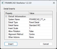 2. Select Panel, Truss, Floor, or Roof for Detail Type, and select an item for Detail Name.
Label walls, trusses, or joists (LA)
| Command name: LABEL | Space(s): Layouts space |
|
Purpose: |
|
|
Usage: |
|
|
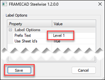
1. Focus on a border with a layout. *To specify a level (if prompted):
2. Click Save. |
|
Move view (MV)
| Command name: MOVEVIEW | Space(s): Layouts space; Detail spaces |
| Purpose: Moves selected items from one border to the same relative location in another border. | |
|
Usage: |
|
|
1. Focus on a border with items to move. |
|
Manual member ordering (ORD)
| Command name: MANUAL_ORDER | Space(s): Layouts (for deep-c joists only); Detail spaces |
|
Purpose: Allows you to set the order in which selected members of a panel or frame (or selected deep-c joists) will be produced by a roll-former at production time. This will override the RFY ordering (as set in BSET) for selected members. |
|
| Usage Focus on a detail sheet (or a deep-c floor layout), then: |
|
| 1. Type ORD and press Enter. | |
| 2. Select members (or joists) in the order that they are to be produced. | |
| 3. Press Enter. | |
|
Steelwise updates labels to reflect changed order. To reset default order or continue manually selecting order: |
|
|
1. Type ORD again and press Enter. |
|
|
2. Type R (reset) and press Enter to reset. |
|
Quick text input (QT)
| Command name: QUICK_TEXT | Space(s): Layouts space; Detail spaces |
|
Purpose: Adds a specified text to a selected location in a border or detail sheet. Allows you to add custom text or remove text. |
|
| Usage: | |
|
1. Type QT and press Enter. A dialog appears. |
|
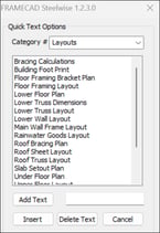 2. Select a category.
Reference point input (REF)
| Command name: REF_POINT | Space(s): Layouts space |
| Purpose: Adds a primary reference point or secondary reference point to a selected location in a border. Reference points ensure that loads transfer from trusses and joists to the underlying walls. | |
| Usage: | |
|
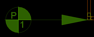
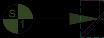
Focus on the border with the lower/lowest-level wall layout, then: *NOTE! If you do not add secondary reference points simultaneously, you must run the REF command again to add a secondary reference for any other border with a layout. Be sure all reference points are in the corresponding location in each border. The reference points appear in layouts with their initial and reference number (i.e., P1, S1). |
|
|
Additional info: • NOTE! Rules for using reference points: 1. A border can have only one reference point. • TIP! Insert the primary reference point at a location where the building outline is the same at each level (i.e., a part of the structure that is common to all layouts). This makes it easier to ensure all layouts align correctly. |
|
Reset registry (RESETALL)
| Command name: RESETALL | Space(s): Layouts space; Detail spaces |
| Purpose: Reverts Steelwise to its default settings. | |
| Usage: | |
| • Type RESETALL and press Enter. | |
|
Additional info: |
|
Revision cloud (REV)
| Command name: REVISION_CLOUD | Space(s): Layouts space; Detail spaces |
| Purpose: Allows you to draw red rectangular border to indicate changes in a border of detail sheet. | |
| Usage: | |
|
1. Type REV and press Enter.
|
|

Section properties and capacities (SECT)
| Command name: SECT | Space(s): Layouts space; Detail spaces |
| Purpose: Shows properties and capacities of various section profiles based on specified inputs. Typically used to provide information to engineers about specified profiles. | |
| Usage: 1.Type SECT and press Enter. 2. Enter/select inputs (e.g., section name, design code, etc.) as required. |
|
Set 3D marker in the Model space (SETREF)
|
Command name: SETREF |
Space(s): Layouts space |
| Purpose: Allows you to copy an entity from the Layouts space to the corresponding location in the Model space based on a 3D reference marker inserted in a layout. | |
| Usage: | |
|
In the Layouts space:
|
|
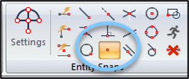 5. Press Ctrl + V and click the 3D marker.
Show entity start point or engineering failures (SHOW)
|
Command name: SHOW |
Space(s): Layouts space; Detail spaces |
|
Purpose: Shows the starting end of a selected entity or if a wall panel, truss or joist has an engineering failure. |
|
| Usage: | |
| 1. Type SHOW and press Enter. 2. To show a starting end: Select an entity and press Enter. To find engineering failures: Press Enter. A colored starburst (asterisk) appears where the entity starts or in a layout or at a detail sheet if a wall panel, truss, or joist has an engineering failure. |
|
Code a support line (SL)
| Command name: TRUSS_LINE | Space(s): Layouts space |
| Purpose: Codes a selected line or polyline as a support for trusses or josts. | |
| Usage: | |
| 1. Type SL and press Enter. 2. Select line(s) to code and press Enter. The lines will change color. NOTE! Steelwise will now treat segments of a polyline as individual lines. |
|
Snap a cursor angle at 45° (SN)
| Command name: SN | Space(s): Layouts space; Detail spaces |
| Purpose: Rotates the cursor crosshairs by 45°. | |
Usage: Type SN and press Enter.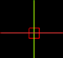 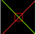 |
|
Spool point (SP)
| Command name: SPOOL_PRINT | Space(s): Layouts space; Detail spaces | ||||||||||
| Purpose: Allows you to print selected borders or detail sheets. | |||||||||||
| Usage: | |||||||||||
1. Type SP and press Enter. A dialog appears.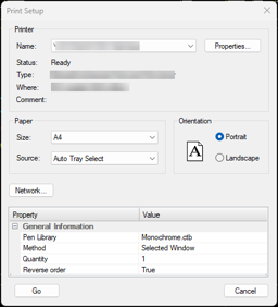 2. Check/select a printer/output (e.g., PDF), size, source and orientation. 3. Check/select pen library, method options*, quantity and print order. 4. Click Go and follow additional prompts as required. |
|||||||||||
|
More info:
|
|||||||||||
Steel profiles (SS)
| Command name: STEEL_PROFILES | Space(s): Layouts space; Detail spaces |
| Purpose: Allows you to add a specified profile to a border or detail sheet. | |
| Usage: | |
| 1. Type SS and press Enter. A dialog appears. 2. Select a profile, member, and other options, and click Draw. 3. Select a location to add the profile. |
|
Software version number (VER)
| Command name: VERSION | Space(s): Layouts space; Detail spaces | ||||||||||||||||
| Purpose: Shows version and licensing information about your installation of Steelwise. Visit Communities to check for and download the latest version. | |||||||||||||||||
Usage: • Type VER and press Enter. A dialog appears with the following items:
The dialog also lists active modules and features. |
|||||||||||||||||