Joist settings (JSET)
| Command name: JOIST_SETTINGS | Space(s): Layouts space; detail spaces |
| Purpose: Framing settings for new* joist frames. | |
| Usage: | |
| 1. Type JSET and press Enter. A dialog appears. | |
| 2. Enter settings in the Layouts tab and Options tab, as needed. | |
| 3. Click Save. | |
Additional info: |
|
|
• *TIP! Any changes you make in the JSET dialog will not affect existing walls. Type LI and select an existing joist to edit its settings. |
|
JSET Layouts tab
| Member Information | |
| System Name | Specifies a data file to use for joist frames. |
| Model Filter | Select Show Only Producible to limit the Model Name field to joist members that can be made with the roll-former selected in Machines Used. |
| Model Name | Sets the joist system (e.g., webbed joist, deep-c), and the profile width and shape, and material thickness and grade to use for joist members. |
| Joist Type |
Specifies what to use for side bearers. Side bearers sit at the perimeter of the frame, parallel to standard joists, and do not typically carry joists. |
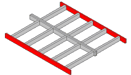
| Side Bearer Type |
Specifies what to use for side bearers. Side bearers sit at the perimeter of the frame, parallel to standard joists, and do not typically carry joists. |
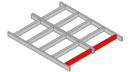
| End Bearer Type |
Specifies what to use for end bearer members. An end bearer sits at the perimeter of a frame, perpendicular to joists, carrying the terminal ends of standard joists. |
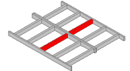
| Int Bearer Type |
Specifies what to use for internal bearers. An internal bearer sits perpendicular to joists and carries terminal ends of joists on both sides. |
| Machines Used | Sets the roll-formers that will be used to make joist frame members. |
| Member Height Override | Sets a value to use instead of the height that is automatically derived from sizing rules (for webbed joists only). |
| Layouts Information | |||||||||
|
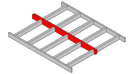
Joist Spacing |
Sets the maximum distance allowed between the center of one joist and the center of the next. | ||||||||
| Int Bearer Spacing | Sets the maximum distance between one bearer and the next. | ||||||||
| Ceiling Batten Spacing | Sets the spacing of ceiling battens along the bottom of joists. Used for bottom chord restraint engineering calculations. Note: A value is required if you want to include batten material in the floor member summary in a border when you type JD to add a joist. | ||||||||
| Reduced Level | Sets the height of the floor system measured from the ground level of the structure to the top chord of the joist. Critical for detailing joist layouts in association with wall framing. Value must be < joist depth, +/- 100mm (3 15/16") of wall height before loads are able to be transferred. | ||||||||
| Bearers Method |
|
||||||||
| Internal Bearer Method | |||||||||
| Double Int Bearers |
Sets each internal bearer to consist of two back-to-back members. |
||||||||
| Oncoming Web Align | Aligns vertical webs with oncoming members (for fixing purposes). | ||||||||
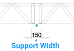
| Double Webs to Supports |
Places two vertical members in a webbed joist at each edge of an underlying support line (as determined by the line’s support width). Type LI and select the support line to adjust its support width. |
||||||||
| Layouts Colour | Sets the color to use for joists. |
| Tooling Options |
| See Panel setting command for info. |
| Applied Loads | In kPa (metric) or psf (imperial) except where noted. |
|
Dead Load |
Dead and live loads of a floor that will be applied to a joist. |
|
Live Load |
|
|
Ceiling Load |
Dead load of a ceiling that will be applied to the bottom chord of a truss. |
|
Snow Load |
Snow load of a roof that will be applied to the top chord of a truss. |
|
Design Point Load |
Vertical load applied to a point on a joist in kN (metric) or kip (imperial). |
| Deflection Limit | |
|
Deflection Limit (Live) |
Preset engineering values. |
|
Deflection Limit (Dead + Live) |
|
|
Max Allowable Deflection |
| Ceiling Battens Information | Used for BOM purposes only, not for modelling. |
|
First Ceiling Batten |
Defines the material and profile to use for the first batten in a truss. |
|
Next Ceiling Batten |
Sets the profile section to use for all subsequent battens. |
|
First Batten Length |
The length of the first batten in a truss. |
|
First Batten Lap |
Length of overlap between first batten and an adjoining batten. |
|
Next Batten Length |
The length of all subsequent battens in a truss. |
|
Next Batten Lap |
Length of overlap between two adjoining subsequent battens. |
|
End Screw Type |
Type/number to use when fixing the ends of a batten to a frame. |
|
End Screw Frequency |
|
|
Int Screw Type |
Type/number to use to fix internal battens to supporting members. |
|
Int Screws per Crossing |
| Creation Options | |
|
Auto Cutting List |
Includes a floor member summary in border in Layouts if joists are labelled. |
|
Auto Label Members |
Adds labels to joist members in the layout. |
|
Preserve Floor Outline |
Keeps the floor outline in the layout. |
|
Auto Floor Sheet Layout |
Includes a floor sheeting layout using Sheeting Information settings in Options tab. |
| Report Options | Sets information to include about joists when you type REP. |
| Select True to for each to include joist Members, Connection Brackets, Connection Fixings, Weight, Battens, and/or Batten Fixings. | |
| Labelling Option Information | (Sets labels and info that appear in a border when you type JD) |
| label prefixes |
Sets what prefix to use in labels for joists, for end, side, and interior bearers, and for bearer beams. |
| Restart Zone Labels |
Restarts from 1 for each zone (if zones are set) (instead of numbering continuously across all set zones). |
| Include Joints | Includes labels when identical members join other members differently or when identical members have different service holes. |
| Include Service Holes | |
| Use Continuous Numbers | Counts from 1 and continues for all joist types (instead of restarting at 1 for each joist type). |
| Collect Common Member |
Shows a quantity for members of equal length (instead of listing all members separately) in a Floor Member Summary. |
JSET Options tab
| Under Floor Information | |
|
Isolated Pier Width |
Sets subfloor settings if needed. NOTE! Sub-floor framing is generally outside the scope of LGS/CFS frame production. |
| Isolated Pier Depth | |
| External Isolated Pier Spacing | |
| Internal Isolated Pier Spacing | |
| Engaged Pier Width | |
| Engaged Pier Depth | |
| Engaged Pier Spacing | |
| Steel Post Type | |
| External Steel Post Spacing | |
| Internal Steel Post Spacing | |
| Post Inground Allowance | |
| Drafting Colour |
| Rough In Options | |
|
Perimeter Options |
Sets rough in options if required. NOTE! Rough in option are generally outside the scope of LGS/CFS frame production. |
| Interior Options | |
| Include Floor Layout |
| Detail Sheet Options | (Sets info to include in detail sheets in joist detail spaces) | ||||||
|
Include Materials |
Adds a bill of materials showing the material, quantity, and length of each member required for the respective joist frame. | ||||||
| Collect Common Lengthts | Lists members in the BOM (and labels members in the elevation view) by common length. | ||||||
| Include Parts | Lists type and quantity of connectors and other parts required for the joist frame. | ||||||
| Include Design Summary | Shows design and load codes, wind speed, and other joist frame design parameters (at bottom of detail sheet). | ||||||
|
Show Major Dimensions |
Includes dimensions for overall size, layout, and geometry. |
||||||
| Show Minor Dimensions |
Includes size, position and spacing of components. |
||||||
| Border Sized to Fit |
Sizes each border independently (instead of using the largest size required for all borders). |
||||||
| Auto Update Dimensions | Sets dimensions to update accordingly for changes you make to a joist frame in a detail sheet. | ||||||
| Dimension Style |
|
||||||
| Show Reactions | Includes reaction values at support points. | ||||||
| Show Percentages | Shows what percentage of the joist frame’s load capacity is being used (instead of just Pass or Fail). Greater than 100% counts as an engineering failure. | ||||||
| Label All Sticks | Shows labels of all joist frame members (instead of just major members). |
| Floor Builder Filters | Sets filters to use by default when you type JJD. |
| Select True to build from Current View Only, or to hide bearers, joists, joist bearers, beam bearers, and/or webbed or non-webbed beams. | |