Panel settings (PSET)
| Command name: PANEL_SETTINGS | Space(s): Layouts space, Detail spaces |
|
Purpose: Sets framing settings for new* wall panels. |
|
|
Usage: |
|
|
1. Type PSET and press Enter. A dialog appears. |
|
|
|
|
|
2. Enter settings in the Panels tab, Openings tab, or Options tab as needed. |
|
|
3. Click Save. |
|
Additional info: |
|
|
• *TIP! Any changes you make in the PSET dialog will not affect existing walls or beams. Type LI and select an existing wall or beam to change its settings. |
|
|
• WARNING! You cannot change the Drafting Width or Offset Distance for a wall after it is drawn. |
|
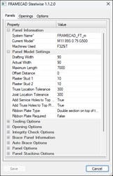
PSET Panels tab
| Panel Information | |
| System Name | Specifies a data file to use for wall panels. |
| Model Filter | Select Show Only Producible to show only profiles that can be made with the currently selected machine. |
| Current Model |
Sets profile width and shape, material thickness and grade for wall panel members. |
| Machines Used | Sets the roll-former that will be used to make wall panel members. |
|
Panel Model Settings |
|
|
Drafting Width |
Sets how wide a wall panel is drawn (for visual and dimensioning purposes). Any intersecting walls will intersect at the wall’s Actual Width. |
|
Actual Width |
Sets the real width of the wall panel, typically equal to the profile width of the section used in the wall (as set in Current Model). Changes to Actual Width will shorten or lengthen intersecting walls by the difference between the Actual Width and the Drafting Width. |
|
Maximum Length |
Sets max wall frame length. An integrity check (IC) can warn you if walls exceed this value. (See Integrity Checks Options.) |
|
Offset Distance |
Sets walls to appear a specific distance from the centerline (in the direction of a selected orientation point) when you draw a panel. |
|
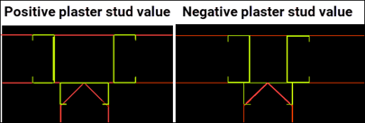
Plaster Stud 1 |
Sets studs to be offset a distance from the face(s) of an intersecting wall to accommodate plasterboard or other lining when (you type PBS or PUA). Positive/negative value moves plaster studs outwards/inwards relative to the intersecting wall. |
|
Plaster Stud 2 |
Sets studs to be offset a distance from the face(s) of an intersecting wall to account for plasterboard or other lining (when you type PAB). |
|
Truss Location Tolerance |
Sets the distance from where a truss or joist lands on a wall within which Steelwise checks for studs. If no stud exists, Steelwise adds one beneath the truss/joist (if required by engineering). This feature is designed to increase structural integrity. |
|
Joist Location Tolerance |
|
|
Add Service Holes |
Includes service holes or truss locator (web) holes in top plates. |
|
Add Truss Holes |
|
|
Ribbon Plate Type |
Adds a specified ribbon type (i.e., double section above top plate; single section above or below top plate) if True is selected for Ribbon Plate Required. |
|
Ribbon Plate Required |
Select True to add a ribbon plate (as specified in Ribbon Plate Type). |
| Tooling Options | |
| Apply lip Notched corners | Uses a lip notch tool (if available on machine) at the ends of members of frames that form a corner. |
| Restrict Swages |
Prevents swaging where members are boxed together.
|
| Plates Over Studs |
Notches a noggin member around a stud member (instead of through the member) when the noggin terminates at a stud. |
| Reversed Tooling | Notches studs (vertical members) and makes plates (horizontal members) continuous, for when plates are required to be structural members. |
| Tabbed | Includes a fixing tab (if available on machine) in track sections in deep C-section floor joists. |
| Use Extra Flange Holes | Punches a hole adjacent to a dimple (if machine has a flange hole tool), generally for double-screwing webbed joists. |
| Use Dual Track |
For detailing frames where a track (or plate) section profile width is greater than the stud section profile width on a machine that can produce C-sections and U-sections, but has no swaging tool. |
|
Opening Options |
|
||||||||
|
Opening Head Style |
|
||||||||
|
LB Webs to Openings |
Sets the maximum width an opening in a load-bearing wall can be before Steelwise automatically adds diagonal webs.
|
||||||||
|
NLB Webs to Openings |
Sets the maximum width an opening in a non-load bearing wall can be before Steelwise automatically adds diagonal webs. Steelwise adds webs even if not required by engineering.
|
|
Integrity Check Options |
Select True for each item to check for when you type IC: |
|
Reference Points |
borders missing a reference point. |
|
Panel Not Coded |
panels not set as Load Bearing, Non Load Bearing, or Structural |
|
Panel Labelling |
panels missing a label |
|
Panel Length Shortage |
panels below practical or required length |
|
Panel Overlaps |
two or more panels occupying the same space |
|
Maximum Panel Lengths |
panels exceeding Maximum Length (set under Panel Model Settings) |
|
Transport Limits |
panels too large for transportation/delivery |
|
Openings Across Joins |
any opening that spans two panels |
| Bracing Over Openings |
any brace that spans an opening |
| Panel Imposed Loads |
panels with no dead load applied |
| Duplicate Labels |
two or more panels with the same prefix and number |
| Show items not detailed |
any panel in the Layouts space that has not been built and has no detail sheet |
| Check Stacks |
extends check to stacks created with the PST command |
| Select All |
Select True to select or deselect all the above items. |
| Clear All |
| Brace Panel Information | |
| Brace Type |
Select Single Strap, Double Strap, K Brace, Bridging Brace, Engineered Wood, or Wallboard Panel. Can be changed later when you type PIB. |
| Stud Bays or strap angle |
Sets how many stud bays the brace type can cross or sets the angle to maintain (for Single Strap or Double Strap only). |
| Strap Material | Sets type to use (for Single Strap or Double Strap only). |
| Auto Brace Options | |
| Load Bearing Wall Frequency |
Adds a k-brace to every specified number of stud bays (e.g., every second, third, etc.) when you type AB. |
| Structural Wall Frequency | |
| Non Load Bearing Wall Frequency | |
| Minimum Wall Height | Adds k-braces only to walls > this value when you type AB. |
| Panel Options | |
| Use LB Clusters | Adds stud clusters where load bearing, structural, or non-load bearing walls intersect. |
| Use ST Clusters | |
| Use NLB Clusters | |
| OH&S Weight Limit |
Adds a warning to the panel's detail sheet if the panel's weight exceeds this value. |
| Panel Stacking Options | Settings for when you create stack diagrams by typing PST |
| Max Height Stack | Sets the maximum height a stack can be before Steelwise creates the next stack (or sets the maximum quantity of stacks Steelwise will create if you select False for Use Height Method). |
| Use Height Method |
Select True to set a maximum stack height. Select False to set a maximum number of stacks. |
| Separate Different Models |
Stacks panels according to their specified model (i.e., profile width and shape, material thickness and grade). |
| Dimension Stack | Adds stack weight, height and length to diagrams. |
| Include ID in XML/FIM | Select True to include stack IDs when exporting. |
| XML/FIM Prefix | Sets the prefix that will be used for stacks when exporting. |
| Show Openings | Includes window and door opening indicators in diagrams. |
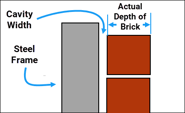
| Brick Gauge Options | (Useful only when openings must be fitted to suit brickwork) |
| Actual Length of Brick | Sets the length (horizontal dimension), depth, and height (vertical dimension) of a single brick (see illustration below). |
| Actual Depth of Brick | |
| Actual Height of Bricks | |
| Brick Joint Width | Sets the vertical and horizontal gaps (perpends) between bricks. |
| Cavity Width | Sets the gap between the brickwork and the wall panel. |
| Brickwork Bond Qty | Sets the brick bond type. Enter 2 for standard brickwork, enter 3 for modular brickwork. |

PSET Openings tab
| Common Setting Information | |
| Window Library | Sets what library to use for aluminium openings when you type AW or AD. |
| Window Auto Offset | Sets the offset to use when you add an opening and select the Auto option. |
| Door Auto Offset | |
| Robe Auto Offset | |
| Floating Stud Gap | Sets an additional clearance in the opening width to accommodate a jamb stud. |
| Prompt Width First | Select True for Steelwise to prompt you to enter a width first. |
| Settings for defined openings | |
| Aluminium Window Information |
Sets head height (distance from panel's bottom plate) and top, bottom, and side clearances for when you type AW or AD. |
| Timber Window Information |
N/A. Not currently in use. |
| External Hung Door Information |
Sets head height and width factors for when you type ED (external door) or PA (passage door). |
| Internal Hung Door Information | |
| Cavity Sliding Door Information | Sets head height and width factors for when you type CS (cavity slider or pocket slider) or FS (face slider or surface slider). |
| Face of Wall Sliding Door Information | |
| Hinged Robe Doors Information |
Sets head height and width factors of hinged robe doors for when you type R1, R2, or R3 and sliding robe doors for when you type S2, S3, or S4. |
| Sliding Robe Doors Information | |
| Nibbed Robes Information |
Sets the head height and the nib length for when you type AR (archway opening or square set opening). |
| Label Options | |||||||
| Label Location |
|
||||||
| Opening label prefixes | Sets the prefixes to use labels for defined openings. | ||||||
| Omit Spaces | Removes the space between prefix and size in labels. |
| Panel settings | |
| Ceiling Panel Options | Specifies a data file to use, AEC Level, noggin spacing, layout color and other options for ceiling, floor, and roof panels. |
| Floor Panel Options | |
| Roof Panel Options |
|
Stud Array |
(Default settings for when you type PSA) | |||||||
| Material Filter |
Select Show Only Producible to limit Material Type options to what can be produced with the machine you are using. |
|||||||
| Material Type |
Select material and profile to use in stud arrays or select Auto |
|||||||
| Starting Position |
Sets the distance of the first stud from the end of a wall and the distance between subsequent studs if you select By Entities or By Points for Stud Insert Type. |
|||||||
| Stud Spacing | ||||||||
| Stud Type |
Set array as Single Stud, Boxed Stud (material must be boxable), Back to Back, or Lip to Lip. Note: Boxed Stud option only appears if enabled by data file. |
|||||||
|
Stud Insert Type |
|
|||||||
|
Opening Option |
Prevents or allows studs to be added in windows or doors.
|
| Notch Settings | (Default settings for adding a panel notch when you type PN) |
| Top Height | Sets the distance from top of notch to top of panel. |
| Bottom Height | Sets distance from bottom of panel to bottom of notch. |
| Notch Width | Sets notch width. |
| Notch Method |
Select Square Method or Angular Method. |
| Labelling Option Information | |||||||
|
Labelling Method |
|
||||||
| Labelling Direction | Sets the corner to start labelling internal walls if you select Directional Method for Labelling Method. | ||||||
| Use Continuous Numbering |
Counts from 1 and continues for all wall types (instead of restarting at 1 for each wall type.) |
||||||
| Restart Zone Numbering |
Restarts from 1 for each zone (if zones are set) (instead of numbering continuously across all set zones). |
||||||
| Ignore Overlay Checks | Prevents Steelwise from automatically moving a label when it intersects with another element. | ||||||
| Prefixes | Sets the prefix to use in labels for each wall type, ceilings, beams, posts, floor and roof panels, and markers. | ||||||
| Disable Sorting | Select True to label walls in order of selection when you type LA. | ||||||
| Use Location Marker | Select True to include with prefix in label indication if wall is external or internal. (e.g., LE1 for Loadbearing External 1) |
| Detail Sheet Options | (Sets info to include in detail sheets in panel detail spaces) |
| Include Materials | Select False to exclude from detail sheets. |
| Include Parts | |
| Include Design Summary | |
| Show Major Dimensions | N/A to wall panels |
| Show Minor Dimensions | |
| Show Engineering Status | tk |
| Hide After to Cad | Select True to hide opening labels, and opening, brace, and stud layers. This makes detail sheets easier for frame assemblers to read. |
| Border Sized to Fit | Sizes each border independently (instead of using the largest required border size for all borders). |
| Include other panels in PPD | Includes Smart Panels in The Panel Builder dialog when you type PPD. |
| Dimension Locations | Select Dimension to Face, Dimension to Lips, or Dimension to Center |
| Panel Builder Filters | |
|
Automatically exclude types of walls or beams; ceiling, floor, or roof panels; or other views from the panel builder dialog when you type PPD. |
|