
Auto brace (AB)
| Command name: AUTO_BRACE | Space(s): Layouts space |
| Purpose: Adds k-braces to walls (based on Auto Brace Options in PSET). | |
| Usage: | |
| 1. Focus on a border with a wall layout. | |
| 2. Type AB and press Enter. | |
|
Additional info: |
|
Auto break panel (PAB)
| Command name: PANEL_AUTO | Space(s): Layouts space |
| Purpose: Breaks up a panel at optimum frame junction locations. | |
|
Usage: |
|
|
• Type PAB and press Enter. |
|
|
Additional info: |
|
|
• NOTE! Prevents breaks in a panel where the distance between two optimum junctions > than the Maximum Length value (as set in PSET Panel Model Settings). |
|
Bath noggin (PBN)
| Command name: PANEL_BATH | Space(s): Layouts space |
| Purpose: Adds a bath/shower as a rectangular object (with a wall noggin at a specified height). | |
| Usage: 1. Type PBN and press Enter. 2. (Optional) change the noggin height. 3. Select a location in a wall layout. Now Steelwise will insert a bath rail at the noggin height when you type PPD. |
|
Build studs (PBS)
| Command name: PANEL_STUD | Space(s): Layouts space |
| Purpose: Adds new studs (and regenerates existing studs*, as needed) in all wall panels across all borders simultaneously but without engineering**. | |
| Usage: • Type PBS and press Enter. |
|
| Additional info: | |
|
• *NOTE! The PBS command does not regenerate locked studs or studs created with the PSA command. |
|
|
• **NOTE! Type PUA to engineer studs. |
|
|
• Steelwise uses default stud spacing from the data file and for the material set for the wall panels. |
|
Calculate bracing (PCB)
| Command name: PANEL_WIND | Space(s): Layouts space |
| Purpose: Calculates bracing requirements for wall panels in a layout and allows you to insert bracing elements and markers, create a bracing plan, and view/export a bracing report. | |
| Usage: With truss and joist layouts completed, roof and floor loads transferred to walls, and reference markers inserted in layouts: 1. Focus on a border with a wall layout.2. Type PCB and press Enter. A dialog appears. 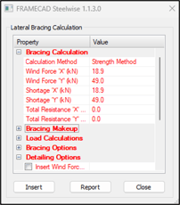 3. To add bracing, change settings (if needed) and click Insert. Or click Report (a new dialog appears) to view, print, or export a bracing report. 3. To add bracing, change settings (if needed) and click Insert. Or click Report (a new dialog appears) to view, print, or export a bracing report.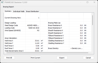 |
|
|
Additional info: |
|
Defined door inputs (various aliases)
| Command name: see table | Space(s): Layouts space |
| Purpose: Inserts an opening with the actual door/leaf width. | |
| Usage: 1. Type a defined door input alias (see table) and press Enter. 2. Set the width and press Enter. 3. Set the insertion method and press Enter. 4. Select a location in a wall layout. |
|
|
Additional info: |
|
| Command name | Alias | Relevant settings in PSET |
| ARCHWAY | AR | Nibbed Robes Information |
| CAVITY_DOOR | CS | Cavity Sliding Door Information |
| EXTERNAL_DOOR | ED | External Hung Door Information |
| FACE_DOOR | FS | Face of Wall Sliding Door Information |
| PASSAGE_DOOR | PA | Internal Hung Door Information |
| HINGED_ROBE1 | R1 | Hinged Robe Door Information |
| HINGED_ROBE2 | R2 | |
| HINGED_ROBE3 | R3 | |
| SLIDE_ROBE2 | S2 | Sliding Robe Door Information |
| SLIDE_ROBE3 | S3 | |
| SLIDE_ROBE4 | S4 |
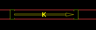
Insert panel brace (PIB)
| Command name: PANEL_BRACE | Space(s): Layouts space; Detail spaces (for k-braces, bridging braces, and strap braces only) |
| Purpose: Adds a specified brace type to a wall panel and automatically changes the orientation of the right-hand stud (if required) for k- and bridging braces inserted in a wall in the Layouts* space. | |
| Usage: 1. Type PIB and press Enter. 2. (Optional) Press Enter again to change brace type or other settings (as set in PSET). 3. Click a location in a wall layout (or click a stud in a detail sheet) to insert a brace. |
|
|
Additional info:
|
|
Lap beam (PLB)
| Command name: PANEL_LAP | Space(s): Layouts space |
| Purpose: Laps a beam over the side or end of a wall by a specified distance. | |
| Usage: | |
| To add a lap: | |
| 1. Type PLB and press Enter. | |
| 2. Specify a distance (if needed) and press Enter. | |
| 3. Click the end of the beam to lap. | |
| To remove a lap: | |
| 1. Type PLB and press Enter. | |
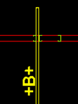
| 2. Click a lapped beam (indicated by a B with + signs) | |
| Additional info: | |
|
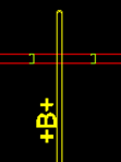
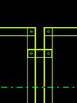
• NOTE! Lapping a beam changes its detailed and reported length. It does not change its apparent length in a wall layout. Steelwise labels a lapped beam in a layout with a + sign indicating each lapped end. • Steelwise automatically inserts a pocket in a wall (i.e., rearranges studs and inserts a horizontal member) to accommodate an intersecting lapped beam when you rebuild studs (PBS) or build panels (PPD).
|
|
Load path (LP)
| Command name: SHOW_LOAD | Space(s): Layouts space |
| Purpose: Shows load paths from trusses or joists to relevant underlying walls. | |
|
Usage: |
|
|
Additional info: • NOTE! The LP command is for information purposes only and is not required for Steelwise to transfer loads. Steelwise transfers loads after you place reference markers and do wall engineering when you type PCB, PPD, or PUA.• Relevant borders must have reference points. • Orange load path lines indicate correct load transfer. • Red load path lines indicate distributed (instead of concentrated) load transfer on structural walls or indicate no load transfer due to a discrepancy in wall heights or between the truss/joist and the wall. |
|
Opening to fit brick (PFB)
| Command name: PANEL_BRICK | Space(s): Layouts space |
| Purpose: Moves an opening to accommodate bricks. | |
|
Usage: |
|
Panel builder (PPD)
| Command name: PANEL_BUILDER | Space(s): Layouts space, Detail spaces | ||||||||||
|
Purpose: |
|||||||||||
|
Usage: To change a wall panel's settings: 1. Double-click a wall panel (in left-hand list). The Panel Properties Editor appears. |
|||||||||||
|
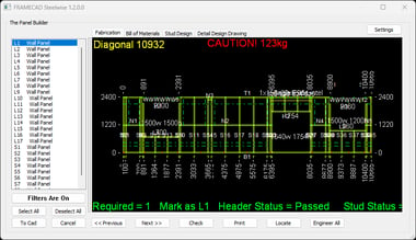
Additional info: • The Panel Builder dialog includes four tabs and common buttons:
• Click Previous or Next to manually navigate panels/beams. |
|||||||||||
 3. Click Filters Are On/Filters Are Off and select True for Current View Only.
Panel draw/panel trace (PD)
| Command name: PANEL_TRACE | Space(s): Layouts space | ||||||||||||
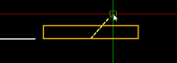
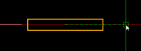
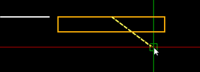
| Purpose: Allows you to draw an uncoded wall panel in a layout. Useful for quickly “sketching” walls that you will likely edit before coding or when you will not know if a wall is load-bearing until after you add upper-level joists and/or roof trusses. | |||||||||||||
|
Usage: 1. Type PD and press Enter. Additional info:
|
|||||||||||||
Panel notch (PN)
| Command name: PANEL_NOTCH | Space(s): Layouts space |
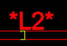
| Purpose: Adds a specified notch (as set PSET) to the selected end of a wall panel. A notch is typically added to allow access to a structural post inserted between wall panels. | |
|
Usage: |
|
 To remove a notch:
Panel reaction plan (PRP)
| Command name: PANEL_REACTION | Space(s): Layouts space |
|
Purpose: Shows the average uniformly distributed load placed on selected panels by supported trusses, joists, and other panels. Also shows point load reactions for jamb studs and from girder trusses and floor joist beam bearers. |
|
|
Usage: |
|
Panel stacks (PST)
| Command name: PANEL_STACK | Space(s): Layouts space |
|
Purpose: Creates a stacking diagram of selected panels based on stacking options set in PSET. |
|
|
Usage: |
|
|
Additional info: |
|
Rake panel (PRA)
| Command name: PANEL_RAKE | Space(s): Layouts space |
| Purpose: Gives the top plate of a wall panel a slope of a set angle. | |
| Usage: 1. Type PRA and press Enter. 2. Click one or more walls to slope. 3. Click two points on a wall to set the slope length. 4. Select the direction of the slope. 5. Enter an angle (maximum 80°). |
|
Show brick (SB)
| Command name: SHOW_BRICK | Space(s): Layouts space |
|
Purpose: Adds a brick setout to selected panels to indicate placement based on Actual Depth of Brick and Cavity Width settings (as set in PSET). |
|
|
Usage: 1. Type SB and press Enter.2. Select a wall and press Enter. 3. (External setouts) select a starting point or (internal setouts) type I and select a starting point. 4. Type SB and press Enter again to remove brick setouts. |
|
|
Additional info: |
|
Show heights (SH)
| Command name: SHOW_HEIGHTS | Space(s): Layouts space |
| Purpose: Adds specified colors to selected panels to indicate panel height. | |
|
Usage: To remove colors: 1. Type SH and press Enter. |
|
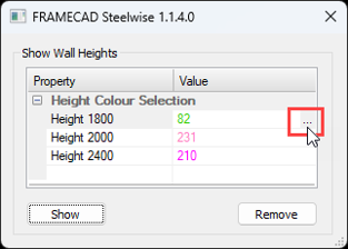 4. Click a height to adjust its color (if needed). Click Show.
Silent panel builder (-PPD)
| Command name: PANEL_BUILDERS | Space(s): Layouts space |
|
Purpose: |
|
|
Usage: |
|
Special noggin input (PSN)
| Command name: SPECIAL_NOGGIN | Space(s): Layouts space |
| Purpose: Adds a specified noggin to a wall layout. | |
|
Usage: |
|
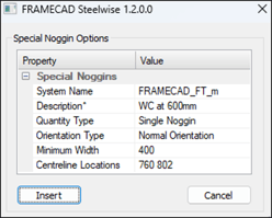 2. Select a noggin from the Description field or set new noggin specifications and click Insert.
Stud array input (PSA)
| Command name: PANEL_ARRAY | Space(s): Layouts space |
| Purpose: Adds one or more studs to a coded wall at specified locations, overriding any existing automatic stud placements. Useful for adding single studs at specific locations or for adding studs for the fixing of cladding. | |
|
Usage: |
|
|
Additional info: |
|
Stud array copy (PSC)
| Command name: ARRAY_COPY | Space(s): Layouts space |
| Purpose: Copies all studs input in a wall layout (using the PSA command) in one border into a second border at the same position relative to reference points. | |
|
Usage: |
|
Update panels (PUA)
| Command name: PANEL_UPDATE | Space(s): Layouts space, truss Detail spaces |
| Engineers all wall panels and updates studs (where applicable*) in the Layouts space, or engineers trusses in a selected Truss detail space. | |
|
Usage: |
|
|
Additional info: |
|