
| Command name: LAYOUT_MANAGER | Space(s): Layouts space, *Detail spaces |
| Purpose: Adds wall panels, beams, posts (i.e., columns), openings, joists, or trusses to a layout using a specified input method (e.g., by turning a selected line into the item, or by drawing the item using points). | |
|
Usage: |
|
|
1. Type ADD and press Enter. A dialog appears. |
|
|
2. Select the tab (wall, beam, post, opening, joist or truss) for the item you are adding. |
|
|
3. Enter or change settings as needed. |
|
|
4. Click Create and insert item(s) in a layout. |
|
|
Additional Info: |
|
Wall tab
| Panel Information |
| Changes (if required) the System Name, Current Model (i.e., profile width, shape and material), Machines Used (i.e., roll-former type), as set in PSET, that will be used to create the panels you are adding. |
| General Values | |||||||||
| Panel Usage |
|
||||||||
| Roof Load | Changes the default roof material (as set in TSET) that will be used on trusses that affect the wall panel(s) you are adding. | ||||||||
| Wind Speed |
Changes the default wind speed or wind category (as set in BSET) that will be used for the wall panel(s) you are adding. |
||||||||
| Wall Height |
Sets the distance from the base to the top side of the top plate of the panel(s). |
||||||||
| Base Level |
Sets the distance from the ground to the base of the panel(s). |
| Width Options |
| Changes the default width options (as set in PSET) for the panel(s) you are adding. |
| Opening Options |
| Changed the default opening options (as set in PSET) |
| Panel Options |
| Changes default options (as set in PSET) for adding stud clusters at wall junctions and other settings. |
| Other Values | |||||||||
| Drafting Colour | Sets the color to use for the panel(s) you are adding. | ||||||||
| Extra Truss Span | Sets the length of an additional or hypothetical truss to determine the load from roofing material (as set in TSET) to apply to the panel(s), in addition to loads automatically detected by Steelwise. | ||||||||
| Truss Pitch | Sets the angle (in decimal degrees) for the extra truss span. | ||||||||
| Extra Floor Span | Sets the length of an additional or hypothetical joist to determine the load (as set in JSET) from a floor to apply to the panel(s), in addition to loads automatically detected by Steelwise. | ||||||||
| Extra Snow Load |
Sets a specific snow load that will be applied to the panel(s) you are adding if an extra truss span is set. |
||||||||
| Stud Arrangement |
Determines how studs will be arranged (when you type PBS or PUA later) in the panel(s) you are adding.
|
||||||||
| Stud Spacing | Sets the maximum distance allowed between studs. This is the value Steelwise uses when you set Stud Arrangement to Single Absolute, Back to Back Absolute, or Boxed Absolute. | ||||||||
| Ext Wall Mass | Sets the force from cladding in kPa (metric) or psf (imperial) when the panel you are adding is used as an external or internal wall. Click the ellipsis (…) to use a dead load calculator to determine this value. | ||||||||
| Int Wall Mass | |||||||||
| Deflection Check |
| Creation Options | |||||||
| Code as you go | Sets panel(s) to be coded (according to option set for Panel Usage) as you create them. | ||||||
| Creation Method |
|
||||||
| Erase original entity |
Deletes the line(s) or polyline(s) you selected to create a panel (when you select By Lines for Creation Method).
|
Beam tab
CAUTION! Steelwise only details beams. It does not calculate their loads, account for their loads in its analysis, nor transfer their loads to structural elements. Please be sure that a qualified engineer designs beams separately.
| General Values | |
|
System Name |
Sets the data file to use for the beam(s) you are adding. |
|
Beam Category |
Sets the type of beam (e.g., Boxspan, Lipped Cee, Webbed) you will add (from options available in the data file selected for System Name). |
|
Beam Name |
Specifies the material/product or material and profile shape that will be used to make the beam(s) you are adding. |
|
Machines Used |
Specifies the type of roll-former that will be used to make the beam members when you select Webbed or Lipped Cee (in some cases) for Beam Category. |
|
Beam Top RL |
Sets the height the reduced level (i.e., the distance from ground level of the structure to the top or bottom of the beam). Changing one value adjusts the other to maintain the value set for Beam Height. |
|
Beam Base RL |
|
|
Beam Height |
Sets the height and width of the product or material/profile set for Beam Name. Changing the Beam Height will adjust the Beam Base RL value. |
|
Beam Width |
|
|
Drafting Colour |
Sets the color to use for the beam(s) you are adding. |
|
Stiffener Beam Options |
Allows you to add a boxed section under the bottom chord and/or over the top chord (when you select Webbed for Beam Category). The beam is adjusted to fit within the set Beam Height. |
|
Treats as Non Structural |
N/A. Do not use. |
|
Detail This Item |
Creates a detail sheet in a Detail space (when you type PPD later) for the beam(s) you are adding, instead of excluding it from the Detail space and removing its label (if one exists) from the Layouts space. |
| Creation Options | |||||||
| Creation Method |
|
||||||
| Erase original entity |
Deletes the line(s) or polyline(s) you selected to add a beam (when you select By Lines for Creation Method).
|
Posts tab
NOTE! You can add a single post or an array of posts. See Creation Options for info.
| General Values | |
|
System Name |
Sets the data file to use for the post(s) you are adding. |
|
Column Type |
Sets the type of post(s) you will add (from options available in the data file selected for System Name). |
|
Column Spacing |
Sets the distance between each post in an array. |
|
Column Top RL |
Sets the reduced level (i.e., the distance from the ground level of the structure to the top or bottom of the column). Changing one value adjusts the other to maintain the value set for Column Height. |
|
Column Base RL |
|
|
Column Height |
Sets the dimensions of the selected Column Type. Changing the Column Height will adjust the value set for Column Base RL. |
|
Column Width |
|
|
Column Depth |
|
|
Use Complex Snaps |
| Creation Options | |||||||||||
| Creation Method |
|
||||||||||
| Erase original entity |
Deletes the line(s) or polyline(s) you selected to add a beam (when you select By Lines for Creation Method).
|
Opening tab
|
Usage: |
|
1. (Optional) Click Settings to change defined opening defaults in the PSET dialog. |
|
2. Select a defined window (under Openings) or defined door (under External Doors, Internal Doors, or Wardrobe Doors) |
|
3. Click Create. |
|
4. Enter dimensions, select insert method, and select a wall to insert the opening. |
Joist tab
| General Values | |||||||||||||||
| System Name | Shows the data file (as set in JSET) for the joist(s) you are adding. | ||||||||||||||
| Member | Sets the material/profile that will be used to produce the joist(s) you are adding. | ||||||||||||||
| Machines Used | Specifies the type of roll-former that will be used to produce the joist(s) you are adding. | ||||||||||||||
| Category | Specifies the kind of joist you are adding (e.g., Webbed Joist, Lipped Cee, or Unlipped Cee, etc.). | ||||||||||||||
| Member Height | Shows the height of the joist (based on options set for Category and/or Member) | ||||||||||||||
| Member Height Override | Sets a value to use instead of the height that is automatically derived by sizing rules (for webbed joists only). | ||||||||||||||
| Usage |
Specifies how the joist(s) you are adding will be used. See JSET for illustrations.
|
||||||||||||||
| Double Member |
Sets the joist you are adding to be a pair of back-to-back joists (instead of a single joist). |
||||||||||||||
| Cut Member In |
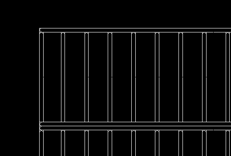
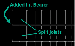
Sets Steelwise to automatically cut back or split in two any joist that intersects with the joist you are adding.
|
| Creation Options | |||||||
| Auto Label Members | Labels the joist(s) you are adding. | ||||||
| Auto Cutting List | Adds a Floor Member Summary to the border where you are adding the joist(s). The summary shows the material, quantity and length of joists. | ||||||
| Creation Method |
|
Truss tab
| System | |
| System |
Shows the data file (as set in TSET) for the truss(es) you are adding. |
| Model Name | Sets the material/profile and orientation (i.e., inline or back-to-back) for the truss(es) you are adding. |
| Machines Used | Sets the roll-former type that will be used to make the truss(es) you are adding. |
| Roof Load | Sets the roofing material (e.g., tile, sheet) that will be installed on the truss(es) you are adding. |
| Hip Method | Sets the type of hip end (e.g., half truss, rafters) that will be used in the layout where you are adding truss(es). (See TSET for more info and illustrations.) |
| Wind Speed | Shows the loads (as set in TSET) that will be applied to the truss(es) you are adding. |
| General Values | |
| Truss Type | Sets the type (e.g., standard, gable, half) of truss(es) that you are adding. |
| Roof Pitch | Sets the main roof slope of the truss(es) you are adding. Click the |
| Ceiling Pitch | Sets an angle (in decimal degrees) by which the bottom chord of the truss(es) you are adding will be raked. |
| Truss Spacing |
Sets the maximum spacing between the truss(es) you are adding and their neighboring trusses. |
| Reduced Level |
Sets the distance from the ground level of the structure to the bottom chord of the truss(es) you are adding. |
| Truss Height | Sets the height (i.e., the distance between the bottom chord and top chord) when you add certain types of trusses (i.e. truncated, parallel). Click the ellipsis (...) to automatically calculate the height. |
| Rail Height | Sets the rail height when you add certain types of trusses. |
| Heel Height | Sets a heel height (instead of using the automatically calculated heel height). Click the ellipsis (...) to display the automatically calculated heel height. |
| Creation Options | |||||||
| Creation Method |
|
||||||
| Add Eaves | Includes an eave with the truss(es) you are adding if a coded roof line is within the value set for Eave Search Distance (in TSET). | ||||||
| Auto Label Trusses | Labels the truss(es) you are adding. |
Add members to frames in detail sheets
| Command: LAYOUT_MANAGER | Space(s): Detail spaces |
|
Purpose: Adds a member to a wall panel, joist, or truss. |
|
| Usage: In a wall, truss, or floor Detail space: 1. Type ADD and press Enter. A dialog appears. 2. Enter or change settings as needed. 3. Click Code As and insert the member in a detail sheet. |
|
| General Values | |||||||
| Material Usage | Sets the type of member (e.g., stud, chord, rail, etc.) you are adding. | ||||||
| Material Name | Sets the profile/material to use for the member you are adding. | ||||||
| Machine Name | Set the roll-former type to use for the member you are adding. | ||||||
| Auto Complete | Labels the member you are adding and re-engineers the panel, joist, or truss after you insert it. | ||||||
| Method |
|