
After you create wall, truss, and joist layouts and detail and engineer panels/frames, you can prepare your project file to be used in the production, assembly, and installation of panels and frames.
This article follows a generic workflow to:
| Add dimensions to a layout |
| Add a 3D view in the Layouts space |
| Create wall panel stacks |
| Clean up your Steelwise file |
| Export files from Steelwise |
Add dimensions to a layout
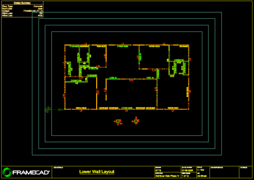
Layouts can be used to provide visual instructions to builders for installing frames onsite. Dimensions help guide builders during installation. This section describes inserting dimensions in a layout using dimension guides.
Reviewing dimension options
Use the BSET command to review or update dimensions settings.
| 1. Type BSET and press Enter. A dialog appears. |
| 2. Click the Options tab and review options under Layout Dimension Options (more information). |
| 3. Click Update to save changes. |
Inserting dimension guides
Use the DG command to add guides. This can make it easier for a builder or others to read dimensions. In the Layouts space, with the relevant layout in focus:
| • Type DG and press Enter. Guides appear around the layout. |
Inserting dimensions
In the Layouts space, with relevant layout in focus:
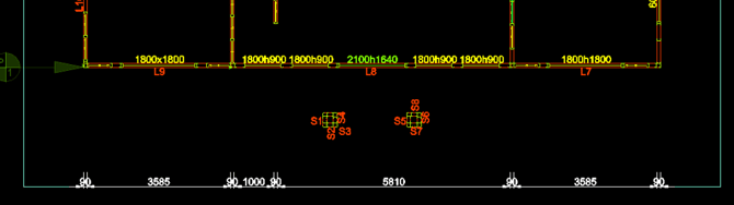
| 1. Type a dimensioning command (i.e., DH, DM, or DV) and press Enter. | ||||||||||
| 2. Select a location to display dimensions. When using dimension guides: | ||||||||||
|
||||||||||
| 3. Select the members or points in the layout to dimension. |
Add a 3D view
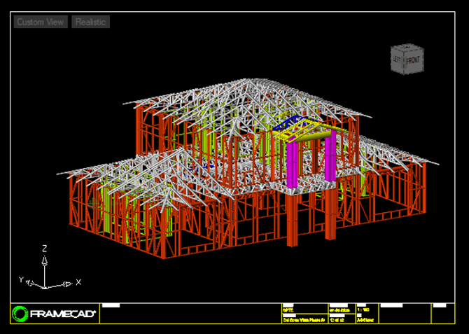
You can include the model of your structure in a border in Layouts to help builders or others visualize the completed structure.
In the Layouts space:
| 1. Type VPORTS and press Enter. |
| 2. Follow prompts to define an area in an empty border to place the 3D model. The model appears in the selected border. |
 |
| 3. (Optional) Double-click the model to rotate, move, and zoom in and out. |
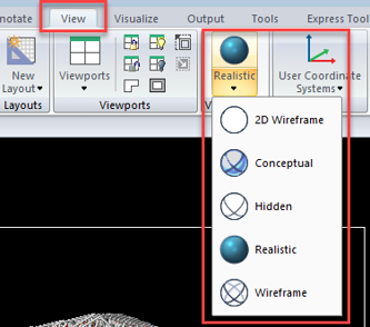
| 4. (Optional) In the Menu bar, click View > Visual Styles to select how Steelwise renders the model. |
 |
| 5. Type PS and press Enter. |
| 6. Right-click the border and select Lock Viewports |
Create wall panel stacks
Use the PST (PANEL_STACK) command to create stacks and stacking diagrams for selected wall panels. Creating a panel stack will affect the order in which a machine produces wall panels (when you export production files).
In the Layouts space:
| 1. Type PST and press Enter. |
| 2. (Optional) Press Enter to change panel stacking options. |
| 3. Select the walls to stack then click a location for the stacking diagram. |
Clean up your file
Before you export files from Steelwise remove any unused borders and purge excess data.
Removing unused borders
| 1. Type BSET and press Enter. A dialog appears. |
| 2. In the Layouts tab, under Client Options, change Quantity to equal the number of used borders. |
Purging data
Purging the file of data can reduce its total size.
| 1. Type PU and press Enter. A dialog appears. |
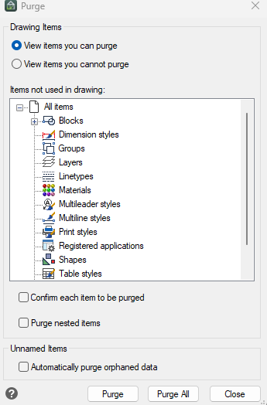 |
| 2. Select items to remove and click Purge or click Purge All. |
| 3. Click Close. |
Export files
You can use various commands to export files for production or other purposes. Common export commands include:
| Command | Info |
| NEXAUPLOAD | send production files to Nexa (for Nexa Base and Nexa Pro customers only) for a for a Nexa user to manage production |
| RFY |
save production files locally for manual upload to a machine |
| PDFSPOOL | save layouts (including stack diagrams, truss uplift plans, etc.) or detail sheets locally for sharing with operators, assemblers, on-site builders, or others |
See How to export files from Steelwise for complete details.