You can start detailing and checking engineering after all wall, truss, and joist layouts are complete (including checking for sufficient bracing and load transfers in wall layouts).
This article describes a generic workflow to prepare for and complete detailing and to start finishing up work on the job file:
* NOTE! You must have the Steelwise Engineering add-on installed to apply engineering and view engineering results.
TIP! It's good practice to create layouts from the ground up and to generate detail sheets from the roof down (i.e., trusses, joists, and wall panels). This helps ensure loads are transferred correctly.
Check wall panels for resistance and add bracing as required
Before you generate wall panels for a wall layout, check that the panels have sufficient wind resistance.
In the Layouts space, with the relevant wall layout in focus:
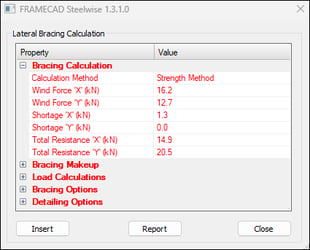
| 1. Type PCB and press Enter. A dialog appears. Text displays in red if resistance is insufficient. |
 |
| 2. (Optional) Click Bracing Options to set sheathing, cladding, or plasterboard options. |
| 3. Click Insert. |
| 4. (Optional) Press Enter to change brace type. |
|
5. Select location(s) in stud bays (i.e., spaces between studs) to place braces then exit command. |
Type PCB and press Enter again to re-check resistance.
TIP! Consider inserting a different brace type if resistance is still insufficient.
Adding a wind force marker or racking resistance marker to a wall layout
In the Layouts space, with the relevant wall layout in focus:
| 1. Type PCB and press Enter. A dialog appears. |
| 2. Under Detailing Options select Insert Wind Force Marker and/or Insert Racking Resistance Marker and click Insert. |
| 3. Select an empty border to place the plan. |
Adding a bracing plan or holding plan in Layouts
In the Layouts space, with the relevant wall layout in focus:
| 1. Type PCB and press Enter. A dialog appears. |
| 2. Under Detailing Options, select Create Bracing Plan and/or Create Holding Plan and click Insert. |
| 3. Select empty border(s) to place the plan(s). |
Check loads correctly transfer to walls
Before you generate wall panels for a wall layout, check that loads from applicable trusses or joists are transferring to walls correctly.
In the Layouts space, with the relevant wall layout in focus:
| 1. Type LP and press Enter. |
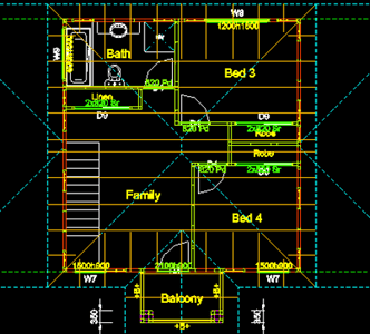
| 2. Click inside the border with the relevant truss or joist layout. Steelwise superimposes load paths over the wall layout. |
 |
| 3. Type LP and press Enter again to hide load paths. Address any load path issue*, as required. |
* NOTE! Red load paths on load-bearing walls indicate loads fail to transfer. This is typically due to a difference in wall height between wall layouts. Address discrepancies and check load paths again.
Generate panels/frames and their detail sheets
Detailers generate detail sheets to review and edit (if necessary) panels/frames to ensure they meet engineering and design requirements. A detail sheet includes the data that machines will ultimately use to create the sticks (i.e., members) to be assembled in a panel/frame.
You can generate detail sheets for truss frames, joist frames, and wall panels by typing the relevant builder command (TTD, JJD, or PPD).
In the Layouts space, with the relevant layout in focus:
| 1. Type TTD, JJD, or PPD and press Enter. The relevant Builder dialog appears. |
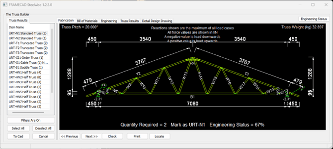 |
| 2. Filter, view, and update panels/frames as required: |
| • Click Filters Are Off/On to filter by view (i.e., by border/layout), zone, etc. |
| • Click to view Engineering Status, Bill of Materials, Truss Results, etc. |
| • Double-click a panel/frame (in the left-hand list) to make changes via its Editor |
| 3. Select the panels/frames (under Results or Members) to generate and click To Cad. |
Steelwise creates a Detail space with a detail sheet for each of the selected panels/frames.
Renaming a Detail space
Double-click the tab for a Detail space, then enter a name in the dialog.

About detail sheets
Each detail sheet includes an elevation view and data about a panel/frame.
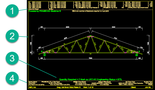
| 1 | Bill of materials and fasteners |
| 2 | Elevation view |
| 3 | Quantity required, zone (if created) and label, and engineering status |
| 4 | Other details (as set in TSET, JSET, PSET, or BSET). |
Reading an elevation view
The elevation view includes panel/frame dimensions, member labels, and tooling indicators (an d other references). Below are the most common indicators and references.
| Tooling or reference | Info | Illustration |
| Dimple | Green octagon | 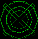 |
| Lip notch | Solid green rectangle | 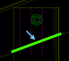 |
| Screw | Green X shape | 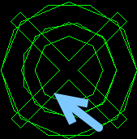 |
| Start of member | Green rectangle at one end of member | 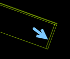 |
| Swage | Four violet, parallel lines | 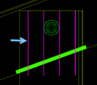 |
| Web notch | Solid red rectangle | 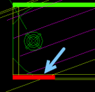 |
| Web side of member | Green rectangle along length of member | 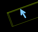 |
| Web triple hole | Solid green square and brown line | 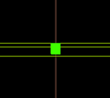 |
Address engineering failures
You may need to edit a panel or frame to correct an engineering failure. A panel/frame fails engineering when one or more design code compliance checks exceeds its allowable limit, resulting in a compliance ratio greater than 100 percent.
NOTE! You must have the Steelwise Engineering add-on installed to apply engineering and view engineering results.
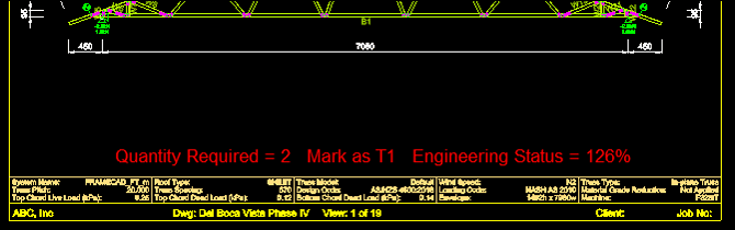
Steelwise indicates engineering failure by displaying the engineering status in red (under the elevation view in the detail sheet).
Locating a failure
In a Detail space, with the relevant detail sheet in focus:
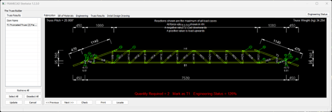
| 1. Type the relevant builder command (TTD, JJD, or PPD) and press Enter. A dialog appears. |
 |
|
2. Click Engineering Status. The elevation view updates to indicate where failure occurs. |
 |
About fixing a failure
In general, you can compensate for an engineering failure by (for joist and truss frames) increasing a member’s material thickness or doubling a member quantity (via an Editor), or (for any frame or wall panel) by adding a reinforcing member via the detail sheet.
Addressing failure via the panel/frame Editor
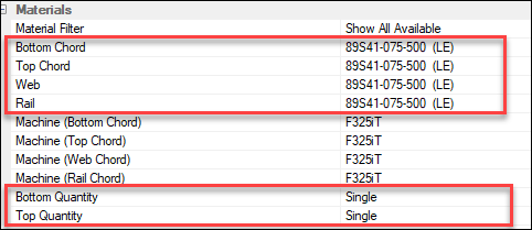
You can use a panel or frame's Editor to increase material thickness, double a member's quantity, or (for joists) change web patterns to address engineering failure.
In a Detail space, with the relevant detail sheet in focus:
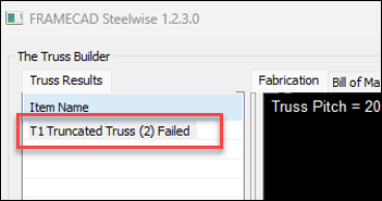
| 1. Type the relevant builder command (TTD or JJD) and press Enter. The Builder dialog appears. |
| 2. Double-click the item name (under Results). The item Editor appears. |
 |
| 3. Scroll down to Materials or Material Information and make changes as required. |
 |
| 4. Click Keep or Amend to apply changes. |
Addressing failure by adding reinforcing members in a detail sheet
Use the BM (TRUSS_BOX) command to insert a boxing member to reinforce all or part of a chord in a truss or joist.
CAUTION! Boxing a chord along its wide axis (i.e., web axis) in a webbed frame will create notch tooling in intersecting webs (for tabbing over the boxed chord). This can leave members' flanges unsupported and at risk of buckling under load when in compression. FRAMECAD recommends boxing chords along the weak (flange) axis and/or consulting an engineer for advice.
Use the LI command to reinforce an opening head with a lintel by clicking Lintel Head for Head Type (under Construction Methods).
Edit a panel or frame as required
Use editing and general commands to move members, add tooling, etc. as required for making design adjustments.
NOTE! Always use the MU (MEMBER_UPDATE) command after you move or change members in a detail sheet. This will update related tooling and engineering.
Common panel/frame editing commands include:
| Command | Info |
| AS | Insert a support point under a truss or joist frame |
| BM | Add a reinforcing member to a selected member |
| C | Copy selected item(s) to specified location(s) |
| ET | Add a tooling action (lip notch, service hole, etc.) to a member |
| IP | Copy properties of a selected item to one or more items |
| IW | Insert web member(s) in a truss or joist frame or in a webbed head in a wall panel |
| LI* | View and edit an item's properties |
| M | Move selected item(s) to a specified location |
| MB | Shorten or break multiple items along a specified break line |
| ME | Extend or shorten selected item(s) to join the side of a target item |
| MF | Set which item joins the other item at a corner |
| MJ | Turn two items joined at an end into a single item |
| MO | Copy an item to a location offset by a specified distance |
| MR | Change the direction from which the item will be viewed in its detail sheet |
*TIP! Double-click a member or its label (for openings) to view and edit its properties.
Create a truss uplift plan
After you generate trusses, address engineering issues, and edit trusses (as required) you can create a truss uplift plan.
In the Layouts space, with the relevant truss layout in focus:
| 1. Type TUP and press Enter. |
| 2. Click inside an empty border to place the uplift plan. |
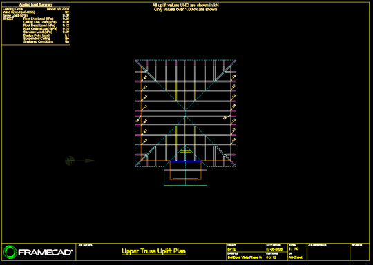
The plan appears in the selected border, showing the upward force (over the minimum value as set in TSET) for each truss, and an applied load summary.