
This article describes a generic workflow for creating a joist layout.
FRAMECAD recommends that you create a wall layout first, then a truss layout (for trusses that affect those walls), thenal a joist layout for joists that will affect those walls. This helps ensure that loads will transfer correctly from trusses and joists to the relevant walls.
TIP! Add a secondary reference point to the joist layout (if one does not exist). The secondary reference point must be at the location corresponding to the primary reference point location.
Draw a floor support line from a floor plan
Start a joist layout by using a polyline to outline the floor area. You will code this polyline as a support line to tell Steelwise where loads will be transferred.
In the relevant layout:
| 1. Draw a polyline that defines the floor area (based on a floor plan). |
| 2. Copy or move the polyline to the border you will use for the joist layout. |
You can now code the polyline as a support line.
Code the floor support line
Code the polyline as a joist support line (to tell Steelwise where loads transfer). With the joist layout in focus:
| 1. Type SL. |
| 2. Click the polyline (i.e., the floor support line). |
The polyline will change color.
NOTE! This is an initial floor support line. You will likely add more support lines based on the joists' load path and on the location of load bearing walls in the underlying wall layout.
You can now set floor boundaries.
Set the floor area boundaries
Use polylines to set floor boundaries, including any void created by a stairway. The polylines tell Steelwise where to place joists when you add them later.
|
1. Draw polyline(s) to outline any void created by a stairway and (optional) for the floor area*. |
| 2. Copy or move the polyline(s) to the joist layout (if necessary). |
*NOTE! You can use the coded support line for the floor area outline, instead. Setting a separate floor area here is meant to reduce clicks when you add joists later.
You can now add joists.
Add joists to the floor area
Use the JD command to add joists within the set floor area boundaries.
CAUTION - Before adding joists - check joist settings (JSET) for the correct System Name (i.e., data file), Model Name (i.e., the joist system, profile and material to use), End Bearer Type, Int Bearer Type , Member Height Override (for webbed joists only), Joist Spacing, Int. Bearer Spacing, Ceiling Batten Spacing, Reduced Level, Bearers Method, Int. Bearer Method and other settings, as required. (Learn more.)
With the joist layout in :
| 1. Type JD and press Enter. |
| 2. Select the boundaries of the floor area (including any stairway void) and press Enter. |
| 3. Select a setout point and joist direction. Steelwise adds the joists. |
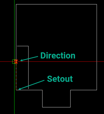
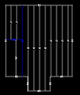
You can now code underlying walls as load bearing (if any were uncoded when you created the wall layout and are now affected by the joist layout) or add support lines to take into account underlying load bearing walls.
Update relevant walls to support joists
After you create a joist layout, you may need to update any uncoded panels (in the underlying wall layout) as load bearing. This allows you to create additional support line in the joist layout.
Showing joist load paths
Use the LP (SHOW_LOAD) command to display joist load paths in its underlying wall layout.
NOTE! The joist and wall layouts must have reference points to use this command.
To show load paths:
| 1. Type LP and press Enter. |
| 2. Click inside the border with the joist layout. |
Steelwise focuses on the relevant wall layout and superimposes load paths from the upper-level joists.
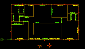
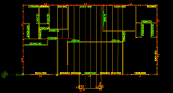
You can now code affected underlying walls.
Coding walls as load bearing
Generally speaking, you will code wall panels as load bearing if they intersect or adjoin joist load paths. With the wall layout in focus:
| 1. Type LI and press Enter. |
| 2. Click panel(s) to be coded and press Enter. |
| 3. Select Load Bearing for Panel Usage and click Code As. |
The panel(s) will change color. Type LP again to hide the load paths.
TIP! Remember to code any remaining, uncoded wall panels in the wall layout as non load bearing and type LA to update wall labels accordingly.
Create additional support lines
You must create support lines (in addition to the initial floor support line) to take into account all underlying, load bearing walls. This helps you to edit the layout so that joists are properly supported.
| 1. Type CSL and press Enter. |
| 2. In the underlying wall layout, click each relevant load bearing wall panel and columns. |
| 3. Click inside the border with the affected joist layout. |
Steelwise superimposes additional orange support lines on the joist layout.
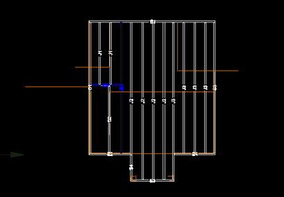
You can now add individual joists and/or edit the joist layout as required.
Add individual joists
You may need to add individual joists to improve on or match design requirements. This includes adding a joist to align with an underlying load bearing wall where a load path exists. You can add an individual joist any time after you run the JD command.
With the joist layout in focus:
| 1. Type ADD and press Enter. A dialog appears. |
| 2. Select the Joist tab. |
| 3. Enter the correct Member, Usage*, Member Height Override (for webbed joists only), Creation Method, and other settings, as required. |
| 4. Click Create. |
| 5. Follow prompts to insert the joist. |
*TIP! Remember that an end-, internal-, or side-bearer must be supported entirely by an underlying wall (when Inline or Under is selected for Bearers Method).
Edit the joist layout as required
Use editing and other commands to move, shorten/lengthen, adjoin, or update usage of joists as required. Commands include:
| Command | Info |
| C | Copy selected item(s) to specified location(s) |
| IP | Copy properties of a selected item to one or more items |
| LI | View and edit an item's properties |
| M | Move selected item(s) to a specified location |
| MB | Shorten or break multiple items along a specified break line |
| ME | Extend or shorten selected item(s) to join the side of a target item |
| MF | Set which item joins the other item at a corner |
| MJ | Turn two items joined at an end into a single item |
| MO | Copy an item to a location offset by a specified distance |
| MR | Change the direction from which the item will be viewed in its detail sheet |
Label joists
Label joists as required (and if Auto Label Members is deactivated in JSET).
With the joist layout in focus:
| 1. Type LA and press Enter. |
| 2. Select joist(s) to label. |
| 3. Confirm or type the starting number and press Enter. |
You can continue creating layouts for additional levels or begin detailing.