
This article describes a generic workflow for creating a truss layout.
FRAMECAD recommends that you create a wall layout first, then a truss layout for trusses that will affect those walls. This helps ensure that loads will transfer correctly from trusses to the relevant walls.
NOTE! The order in which you create layouts will vary according to design. For example, if you have a two-story structure with a two-level roof, you will create the lower wall layout first followed by the lower truss layout, then create the upper truss layout after you create the upper wall layout.
It helps to conceive a roof as a series of rectangles or roof blocks (more info) that require trusses. Detailers working on simple roof shapes can automatically add trusses. But generally, for each roof block, detailers will need to:
Create a truss support line
Offset the support line to create an eave
Code the support and eave lines
Create internal roof lines
Add trusses
Draw a truss support line from a floor plan
Start a truss layout by using a polyline to indicate the external load-bearing walls that will support the trusses. You will code this polyline as a support line later to let Steelwise know where loads will transfer.
In the relevant layout:
| 1. Draw a polyline over the external load-bearing walls (in a floor plan) that support the trusses. |
| 2. Copy or move the polyline to the border you will use for the truss layout. |
You can now create a roof line (i.e., an eave), if required.
NOTE! You may need to code internal load-bearing walls as well. Use the CRL command.
Offset the truss support line to create a roof line
Use an offset command to create a roof line (i.e., an eave line) that will be offset from and parallel to the truss support line. You will code this line later as a roof line.
With the truss layout in focus:
| 1. Type MO or O and press Enter |
| 2. Enter the offset distance (i.e., the width of the eave) and press Enter. |
| 3. Click the polyline (i.e., the truss support line). |
| 4. Click the direction of the offset. |
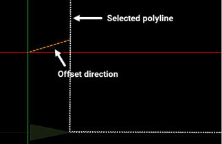
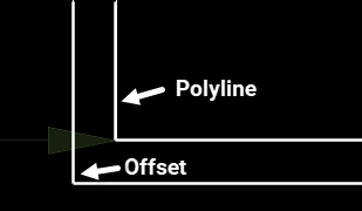
You can now code the support line and roof line.
Code the truss support line and roof line
Code the polyline as a truss support line (to tell Steelwise where loads transfer) and the eave as your roof line.
Focus on the truss layout. For the truss support line:
| 1. Type SL. |
| 2. Click the polyline(s) to code and press Enter. |
For the roof line (eave):
| 1. Type RL. |
| 2. Click the offset line(s) to code and press Enter. |
The lines will change color and type
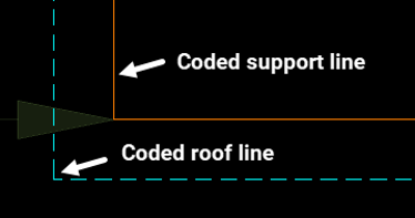
You can now create internal (i.e., ridge, gable, valley etc.) roof lines.
Create internal roof lines
Set the width (i.e., the width of the roof end), length, and roof type to apply to one or more roof blocks (following Steelwise’s roof theory).
For each roof block in the truss layout:
| 1. Type CRL and press Enter. |
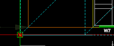
| 2. Set the roof block width: click one corner of the roof line at one end of the roof. |
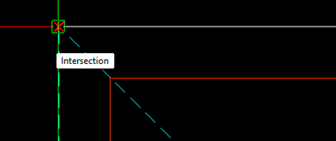 |
| Then click the other corner of the roof line (at the same end). |
 |
| 3. Set the roof block length: click either corner of the roof line at the opposite end of the roof. |
| 4. Set the roof type: type the relevant letter (Gable, Hip, etc.) for each end of the roof, as prompted. |
| 5. Enter additional settings as prompted. |
Steelwise adds the internal (i.e., ridge, gable, valley, etc.) roof lines.
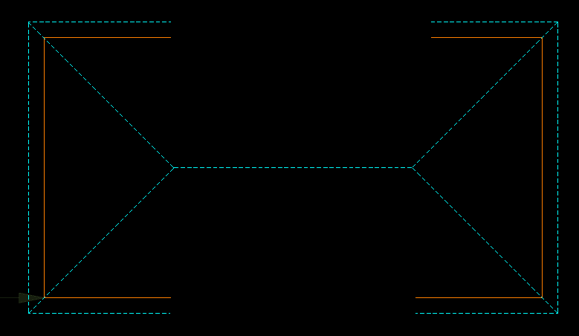
You can now add trusses to the roof block.
Add trusses to roof blocks
Add trusses by setting the width and length of the area over which the trusses will be placed, then selecting the roof type for each end. This is generally indicated by the extent of the roof support line for a roof block.
CAUTION - Before adding trusses - check truss settings (TSET) for the correct System (i.e., data file), Model Name (i.e., back-to-back, inline), Roof Load (or material type i.e., sheet, tile), Roof Pitch, Sub Pitch (for hip or valley ends, if different from roof pitch), Wind Speed, Reduced Level (i.e., elevation relative to the structure’s ground level), Hip Method, Eave Options and other settings to apply to the trusses. (Learn more.)
For each roof block in the truss layout:
| 1. Type TD and press Enter. |
|
2. Set the width: click a corner of the support line for the first point, then click the other corner (at the same end) for the second point. |
| 3. Set the length: click the support line for the third point. |
| 4. Type the letter for a roof type (i.e., Gable, Hip, etc.) for one end, as prompted. This must match the type selected when you created internal roof lines. |
| 5. Type a letter for a roof type for the opposite end, as prompted. |
| or |
|
If only setting up one roof end, type M and press Enter for more options. A dialog appears. Select the relevant option (e.g., Truss Only). |
|
|
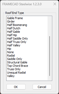
Steelwise adds trusses to the roof block.
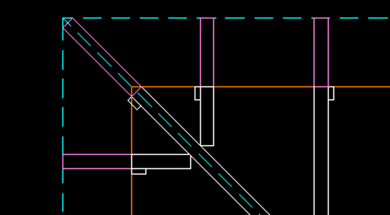
NOTE! A rectangle appears on each truss indicating the side from which the truss will be viewed in a detail sheet in Detail spaces (when you type TTD ).
You can now edit the truss layout and label trusses (if auto labelling is disabled in TSET).
Edit the truss layout as required
Use editing and general commands to move, copy, break, extend, etc. trusses, as required, ensuring that trusses have the correct length and properties, and more. Commands include:
| Command | Info |
| C | Copy selected item(s) to specified location(s) |
| IP | Copy properties of a selected item to one or more items |
| LI | View and edit an item's properties |
| M | Move selected item(s) to a specified location |
| MB | Shorten or break multiple items along a specified break line |
| ME | Extend or shorten selected item(s) to join the side of a target item |
| MF | Set which item joins the other item at a corner |
| MJ | Turn two items joined at an end into a single item |
| MO | Copy an item to a location offset by a specified distance |
| MR | Change the direction from which the item will be viewed in its detail sheet |
Label trusses
Label trusses as required (and auto labelling is disabled in TSET).
With the truss layout in focus:
| 1. Type LA and press Enter. |
| 2. Select the trusses to label. |
| 3. Confirm or type the starting number and press Enter. |
Insert a secondary reference point
Add a secondary reference point to the truss layout (if one does not exist). The secondary reference point must be at the location corresponding to the primary reference point location.
Now you can create a joist layout (if required) for a floor that will affect a wall layout you’ve already created.